E-series (EMC)
Benefits of MCT Brattberg E-series systems
- Protects against electrical and magnetic interference (EMI), “bugging”, electronic sabotage (SEMP) and static electricity (ESD).
- Assists cable management.
- Integral earthing between cables and wall screen.
- Also seals the penetration against the passage of fire, water, gas, sound and environmental hazards.
- Special E-Series for Grounding and Bounding
- System can be dismantled and re-used.
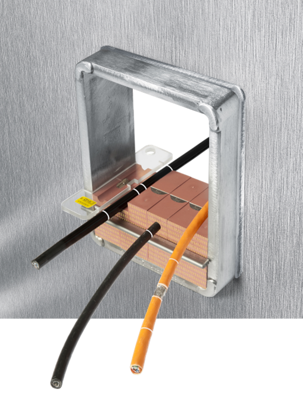
The EMC secret is a tempered metal sheet which systematically stops electrical current from passing along the cable screening through the seal and successfully function as an extended wall screen.
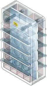
- All dimensions are exactly the same for the standard MCT Brattberg components.
- All Insert Blocks are marked with yellow marking (see instructions).
Hazardous areas
Cable and Pipe Penetrations exist whenever services are routed through walls, floor, decks or bulkheads. In an
emergency situation these penetrations could allow the passage of hazardous such as fire, water and gas. The unique MCT Brattberg System has been approved by all leading Marine and Civil Authorities as a certified
method of sealing such penetrations. The MCT Brattberg system is a Multipurpose seal designed to allow penetration without compromising the security of the construction. Each and every cable and pipe is lead through a frame by its own pair of halogen free module blocks which are then sealed by the use of a compression system.
Historically, protection of buildings, personnel and equipment from lightning was achieved by the use of lightning conductors. These measures, however, are inadequate as they provide protection from fire and personal injury only; to eliminate the Electromagnetic Interference (EMI), sometimes known as electronic smog, protection must be more specific. The protection is achieved by a means known as Electromagnetic Compability (EMC) giving both external and internal interference protection. The MCT Brattberg system is available in a specific E-version which include both the EMI and EMC-version. Around and in close proximity to every electrical conductor exist a magnetic field. This magnetic field generates/interferes with the current flow, known as induction.

Such induction fields can easily cause important information to be destroyed and, in extreme cases, affect the electronic equipment. The ability of any cable to intercept such energy depends on how and where it is installed, on its connection to other units and on its construction. The cables screening properties, therefore depend closely on the cable shielding. The cable screen is able to dissipate and absorb magnetic interference fields, therefore protecting its core conductor. These electromagnetic interference pulses can be discharged from screen to earth.
The MCT E-Series contains a sprung copper sheet which prevents transfer of interference in the cable. Consequently, every MCT E-Transit also works as an extended wall screen.
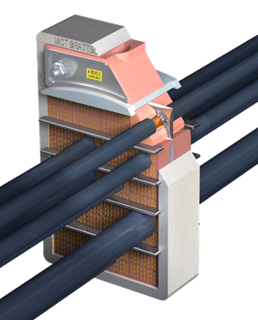
Design
As with all MCT Brattberg products, the MCT Brattberg E-system comprises of a modular sealing system installed in a frame and sealed by compression system. Uniquely, however, the MCT E-system contains features which ensure earth continuity and screening through the penetration. Frames are welded into the wall structure to give earth bonding. For round penetrations a steel sleeve is welded to the structure prior to the installation of the RGP transit. MCT E-Blocks have the facility to screen and earth cables and pipes when installed in such frames. Stayplates are used to key blocks into frames and aid continuity between module blocks. The presswedge whilst compressing the system, give the facility to allow full screen and earthing bond.
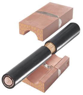
The E-MCT blocks consists of 2 different materials:
- The special developed rubber material Lycron is halogen free and gives the advantages of fire resistance, low smoke emission, heat insulation an excellent chemical resistance.
- The integral copper sheet allows the discharging and shielding protection between the cable and the system. In order to achieve continuity approximately 10 mm of the outer cable insulation must be removed. The exposed braiding must be placed in the center of the insert block.